| Renders & Downloads | Who is & Info | Links | Home |
|
PART 1, Creating a refence setup scene |
||||||
|
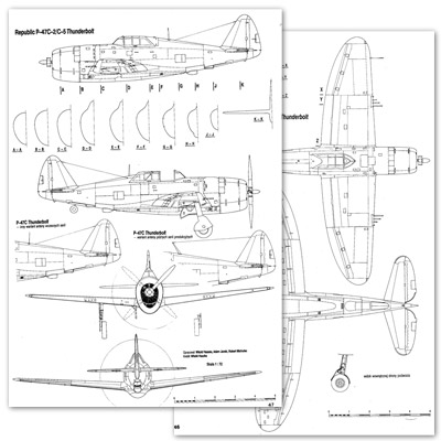
Before we start modeling our aircraft we need some sort of aid that will help us
get the shape and proportions right. Without a proper reference setup this would be
very difficult. All kind of blueprints are available on the net. My favourite source is www.airwar.ru.
|
||||||
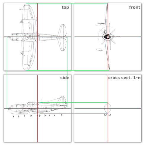
Aligning the planes Create 3 new planes, one for the bottom view, one for the side view and one for the front view. Apply the top, side and front textures and align the planes so that the red lines meet (marked with green circles). Make the planes editable and delete the polygons you don't need. 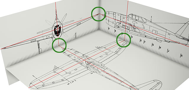
Setting the shader/texture preview properties To be able to view the blueprints even if you are in wireframe mode you need to add a display tag to the planes. Edit the display tag and check "use shading mode Guarag shading". This is not all. The blueprints are visible but very blurred/low res. Put the blueprint texture in the color channel and set the "texture preview size" to 1024*1024 in the illumination channel. Now the blueprints should appear as sharp as in the image below. 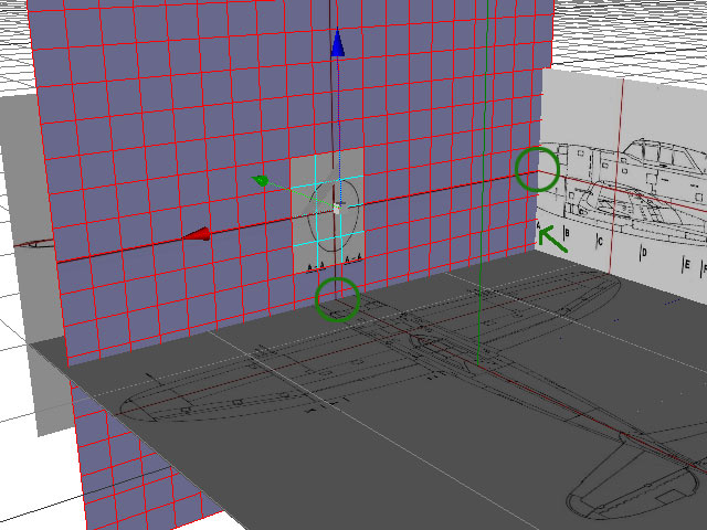
Setting upp the cross sections The above image shows how the cross sections are set up. Create a new plane and apply one of the cross section textures (don't forget to use the shader setting I described in the previous paragraph). Align the plane so that the red lines meet (marked with green circles) and move the plane into position. The green arrow shows that cross section "A" is moved into the place where "A" is marked on the side view. Delete all the polygons from the cross section plane that you don't need. 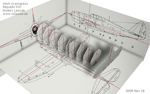
Repeat the procedure for each cross section until you have something that looks like this. The reference setup file is available for download in the next chapter if you wish to download it instead of creating it yourself. NEXT CHAPTER: Modeling! |