| Renders & Downloads | Who is & Info | Links | Home |
|
PART 2, Modeling |
||||||||||||||||||||||||||||||||||||
|
On this page I have tried to explain my work process while modeling the P47. I have probably made a lot of mistakes along the way and I'm not working "by the book" - I'm just a happy hobbyist! You are more than welcome to mail comments and suggestions and I will add them to this page.
I'm writing this primarily with C4D users in mind but users of other 3D apps should be able to follow the work process. If you are a Wings3D user then you can simulate the hypernurbs with a mesh subdivision trick (select the polygon edges and set them to "soft", then subdivide). |
||||||||||||||||||||||||||||||||||||
You can download the reference setup file (.cd4 & fixed drawings) from [HERE] if you wish to tag along!
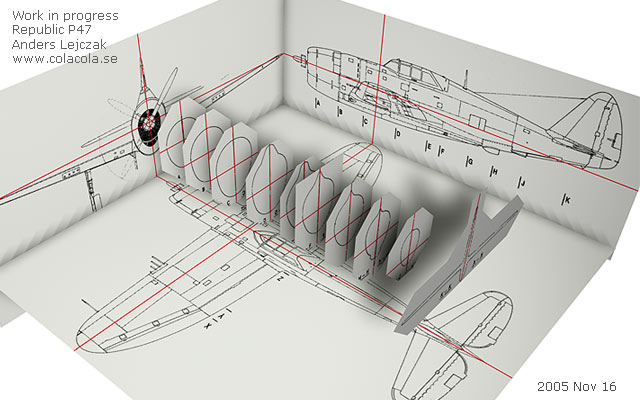
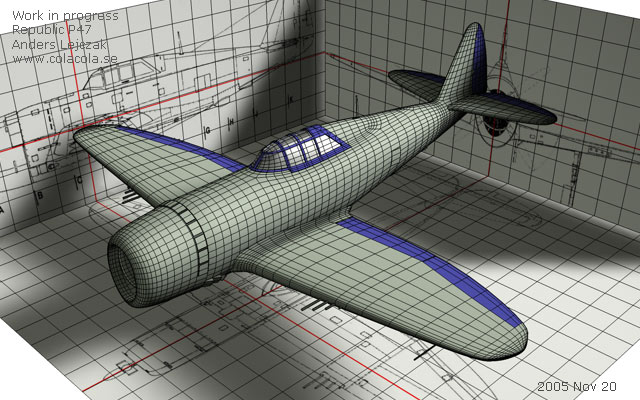
Created a reference setup using drawings from www.airwar.ru. This is an important step that involves some 2D work. It's very importat that everything is aligned and in the same scale. I've painted the red lines to make sure that that all planes and cross sections are placed in the correct places. 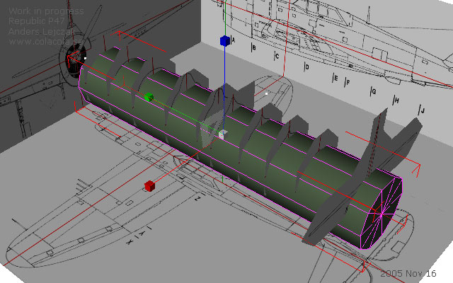
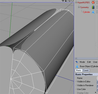
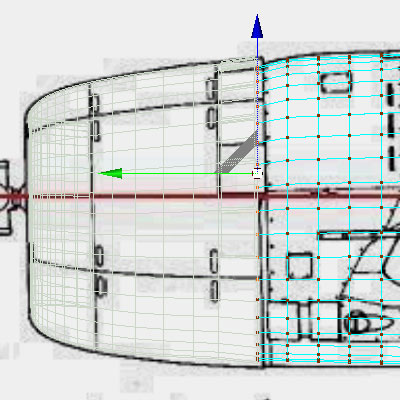
Now we need to start with a suitable shape. 10-sided cylinder fits this purpose. I'ts always easy to add polygons if we need more - removing them is much harder. Question from visitor: Is the length of the 10 sided cylinder the same as the fuselage length? It's hard to tell from the screen grab. Answer: Yes roughly - no need to make it exactly the same length because we will adjust the point in both ends along the way. 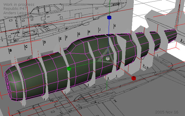
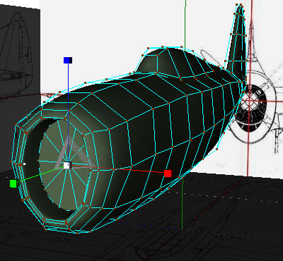
I've sliced the cylinder vertically couple of times and extruded the polys where the cockpit should be. Then I have moved polys by hand to create the shape you see in this picture. I'm constantly switching between top view, side view and free view to make sure that my mesh has the same shape as the drawings. The cross sections are really helpful in this step. Question from visitor: I was curious why you chose not to use Loft Nurbs and create the frame splines for it... Answer Wings3D, where I come from, doesn't have nurbs so I'm used to work with boxes. This is probably not the most efficient way but creating splines along the cross sections & profiles take me much longer time than shaping the mesh from a box or simple cylinder (in this case anyway). I tried lofting but found out that I have less control over the polys in that way. This probably has to do with my limited skills in that area. I've made the reference setup file downloadable from the top of this page. So if anybody would like to show alternate solutions and approaches I would be more than happy!
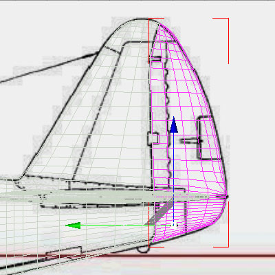
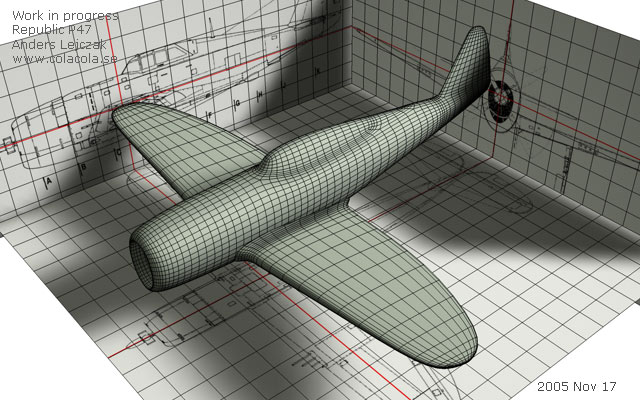
In this step I have made a new cut just in front of the tail and extruded the tail fin. I've also put the cage into hypernurbs. 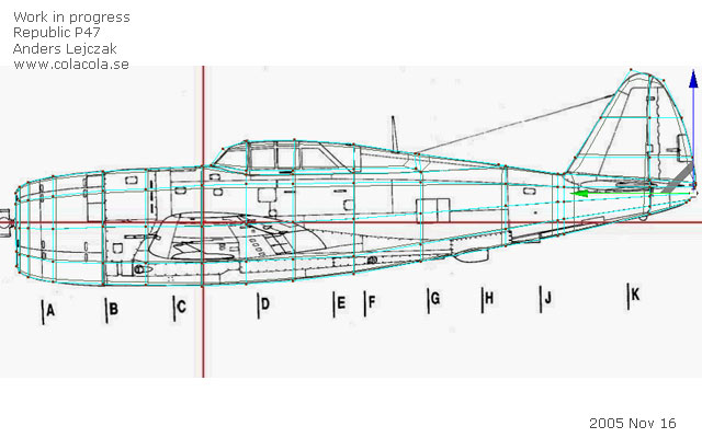
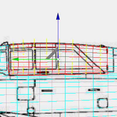
As you can see in this picture I have already begun thinking of where I will cut out moving parts later on. I have therefore aligned the polys around the cockpit and also made a vertical cut by the rudder. Question from visitor: The point view screen grab appears to have 15 vertical knife cuts. Is this correct? Answer: I haven't counted. You can make as many/few cuts as you please. The important thing is that you have enough cuts to create the intended shape and that your lines/polygons "follow" the shape of the airplanes body.
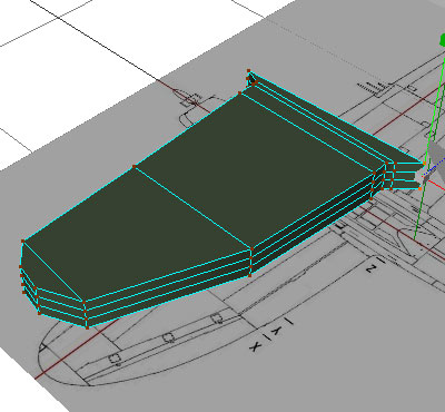
Question from visitor: Are the wings extruded from the body or created from unattached boxes as the tutorial seems to indicate? Answer: The wing (it's only one but I have put it into a symmetry object) is created from an unattacehd box in this case. I have however extruded the wings when I created some of my previous (the Spitfire, the Dornier and the J29 jet) and newer (the P38 and the P40) models. Extruding is better but requires more skill. This tutorial is not for pros so I have described the easier solution.
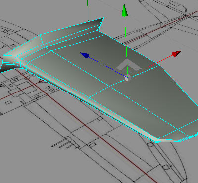
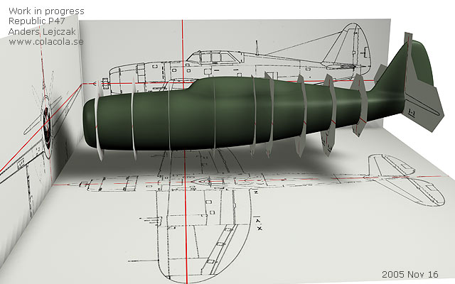
Now throw to wing into hypernurbs and then into a symmetry object. It's starting to look like something but it still needs some tweaking to get the shape right. "Freeze" your hypernurbs (make editable mesh) when you're satisfied with the fuselages shape. Question from visitor: When you "freeze" the HN to get the polygon geometry, what's your Render sub-division value? Answer: the sub division value is set to 2. If I notice that the poly count is too low somewhere then I fix it by adding a cut before I freeze the mesh. Question from visitor: I was wondering why you "freeze" your mesh? I would think this would make it tough to edit later on. Is it a performance issue Answer: No I don't freeze the mesh because of performance but because I try to keep the poly count down and the mesh clean. I only freeze it once I'm happy with the basic shape and before I start cutting out and/or intruding/extruding details. If you start cutting out details and extruding details while still in hypernurbs then your poly count will explode. It is always easier to add polygons than remove them. 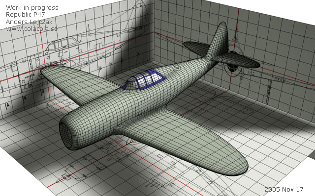
I used exactly the same approach when creating the tail wings. As you can see I have also finished the cockpit - it's pretty simple actually. I will explain how in the next step....
Question from visitor: I'm having difficulty in copying the canopy polygons. I select the polygons, go to the structure manager and insure that I'm in the polygon mode. Then I hit the edit tab & select "copy". I hit the edit tab again but click on "paste" this time. Now I have twice the original number of polygons but the copy is still attached to the fuselage. Any idea what I'm doing wrong? I tried copying and pasting in the point mode and am able to move the group points around freely. Can't do it with polygons though. How did you do it? Answer: I have done it in this way:
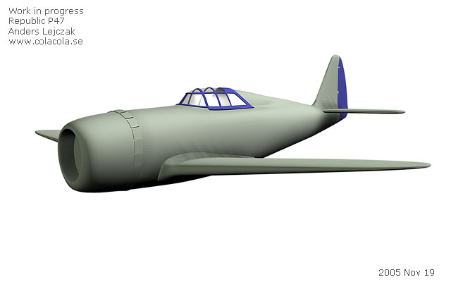
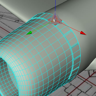
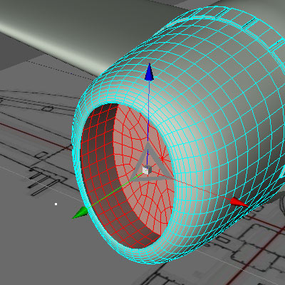
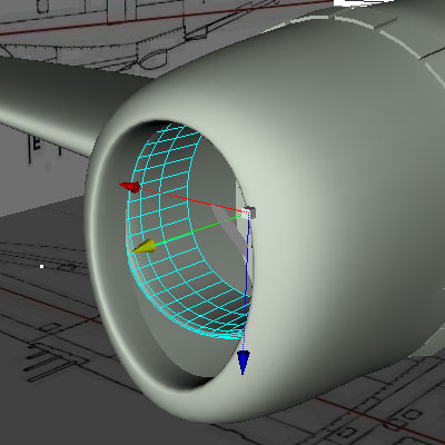
My next step is the separate the rudder and the part that covers the engine (the cowling) from the rest of the body.
Now lets work on parts that should be movable (flaps, pitch, ailerons etc). Make sure that you are satisfied with the wings shape before you convert the hyper nurbs object into a mesh (make editable). Proceed exactly in the same way as when creating the rudder. Go to top view and align your polys/points so that you won't have to make unnecessary additional knife cuts. Select and copy the polys you need for the ailerons, flaps etc and create new unattached objects. Delete the corresponding polys from the wings when done. I have colored the separate objects blue just to illustrate. You may have noticed that I have begun adding details to the fuselage (stuff that sticks out). This is simply done by selecting polys (or groups of polys) and making inner intrudes and extrudes. I would suggest that you make a google search for P47 reference photos and decide on a detail level that will meet your specific needs. 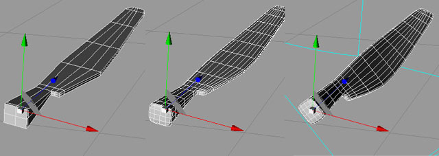
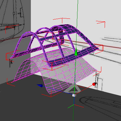
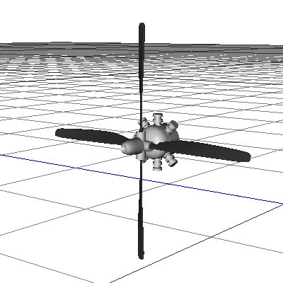
The propellers blades can be a bit tricky but I have approached it basically in the same way as when I created the wings. First I did a rough shape based on a sliced box that I put into a hyper nurbs object (subdivision = 1). I then put the hyper nurbs object into a twist deformer and twisted it about 45 degrees.
 Coming up next is the undercarriage. I have basically made it out of a couple of sliced boxes and cylinders. The wheels are tori that I have flattened a bit in the middle. Google for "P47 wheel" or "p47 landing gear" and you will find photos that will help you get this part right. 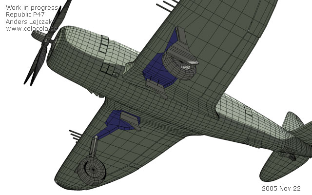 I wasn't sure about the shape of the compartment that holds the undercarriage so I had to go back to ww.airwar.ru and located a P47 drawing showing the aircraft from the underside. I made a new reference drawing out of it and made a new reference plane showing the aircraft from below - I now had a shape I could follow. I shaped the undercarriage compartment (blue area) by moving points - no need for new knife cuts. Then I selected the shaped polys and intruded + extruded them. Extrude more than I have in this picture because the compartment looks too shallow. You can add more details if you wish but I will do it when texturing. 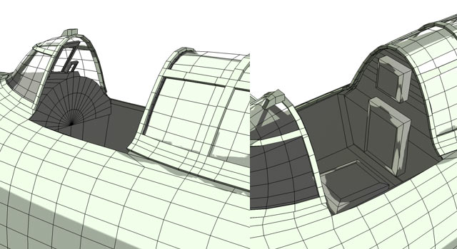 This picture shows how the cockpits interior looks like. It's pretty simple but add a few details and it will do once it is textured. Now… before we move on to the next chapter and UV-map our little model take some time and inspect your mesh. Fixing stuff in the mesh can be tricky later on. Do you have all the details you need? I will for example take a second look at the propeller (blades and hub), the engine, the cockpit interior and the undercarriage. 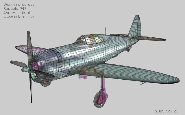 I've corrected some small details in the mesh and I have also now already UV-mapped it. The next step will be to texture it (now this is the fun part). 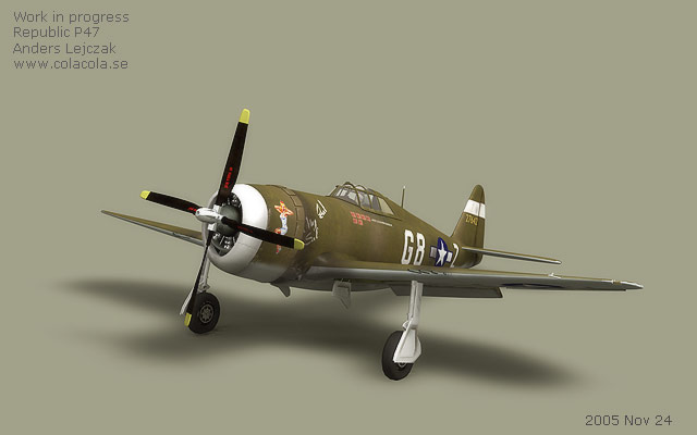 Here's a textured version. NEXT CHAPTER: UV-mapping & texturing |