|
|
| |
Who is this for? This page will probably be most useful for those who have tried & failed
using body paint (or never used it) - not for those already using it. I have received a comment telling me to "instead of building plastic toy planes" should "model and texture each panel individually".
Have that in mind before blindly following everything I have written :)
Tools you need: An editor that handles layers (Photoshop, TheGimp or alike) and a UV-mapper - BodyPaint.
Creating the base for the UV-template.
Fire up your 2D editor and create a new 2048*2048 document. Fill it with white and save it as "uv-template.jpg".
Create a new material in C4D and apply the "uv-template.jpg" in the color channel. Apply this material to _all_ objects (not to lights and environmental objects if you have any).
Preparing the mesh
Before I plunge into UV-editing the mesh I will fix a couple of small things that will make the UV-editing easier.
I have connected all objects that don't need to be individual objects (for example the fuselage with the fuselage details).
I have also connected the wings with all the flaps and ailerons. Why? Because it is _much_ easier to separate these object again later than UV-edit all these objects separately. Consequently I have connected the tail wing with the pitch.
Take a look at my object list [HERE] if you wish.
Setting selection tags
The selection tags are a must. Why? Because they will help you select specific polys or areas of polys while you UV-edit your mesh. Set selection tag on areas that will need special attention or are difficult to select.
I have selection tags on the following objects:
- Fuselage (a tag for all left side polys, a tag for all right side polys and a tag for the inside if the cowling).
- Wings (a tag for the top side and a tag for the bottom side)
- Tail wings (a tag for the top side and a tag for the bottom side)
- Instrument panel (a tag for the dashboard polys)
- Rudder (selection tags for the left & right side polygons)
This is how you set a selection tag (on the fuselage for example):
- Select all polys on the left side using the usual selection tools.
- From the select menu choose "set selection" (a red triangle appears next to the fuselage object). Name your selection "leftbody"
- Invert your selection (now all polys on the fuselages right side should be selected)
- BEFORE you create another selection tag make sure that you deselect the previous one - otherwise it will be overwritten with the new selection. I do this
irritating mistake all the time. Deselect the "leftbody" tag by clicking on the fuselage object in the object hierarchy. The polys on the right side of the fuselage should still be selected -
now set another selection tag (a second triangle should appear next to your fuselage object) and name it "rightbody".
|
UV-editing
Now to the actual UV-editing! Switch to UV-Edit mode (by selecting this option from the layout menu).
Our approach will be to begin with the large object and continue with the smaller. Let's UV-edit the fuselage.
- right click on the texture/material (the blank white one we created) and select load texture (the texture now also appears in the top right 2D view, i.e it turns white)
- set the brush size to 2
- set the brush color black
- select _all_ polygons on the fuselage
It looks like a mess (the pict to the right) but don't worry.
|
|

|
- click on "start interactive mapping"
- use the rotate/scale tools to well.. scale and rotate the UV until it looks like in this picture.
- Click on "stop interactive mapping"
- Don't deselect!
- Click on the "Use UV-polygon Edit Tool" (if you are not sure which this is then move your pointer over the different tools - their names pop up in the lower left side of your screen).
- Select "Outline Polygons" from the "Layer" menu (this carbon copies the polygons onto your texture)
|
|

|
- Double click on the selection tag "bodyright"
- Click on the "Move tool" and move the selected polys up into position as shown in this image.
- Select "Outline Polygons" from the "Layer" menu.
- Tadaa.. you now have UV-mapped the fuselage into one left and one right side.
|
|

|
Proceed in exactly the same way when UV-editing the wing. Keep in mind that you need the reserve space for all other objects as well. Don't forget your selection tags (for example the dashboard).
When you have gone through all your objects you should have a UV-map similar to this.
Save and the UV-map will replace the blank white texture you created at start.
|
|

|
Question from visitor:
When I use BodyPaint I always UV-edit and texture the low-poly cage while it's still in a HN and I noticed that you don't - why not?
Answer:
Hmmm... I have never thought of doing it in that way. Probably because I (still) see modeling and UV-editing as 2 separate steps. More experienced users maybe integrate modeling and UV-editing more than I do in the work process. I see your point though and will try that approach next time.
However - before I start UV-editing I like to connect as many objects as possible. I have for example connected the fuselage with the cowling and a number of fuselage details. In this way I will only need to UV-edit one object (The Fuselage) instead of say 5-7. This makes the UV-editing a lot easier but I cannot connect objects if they are a mix of hypernurbs, primitives and editable meshes.
Question from visitor:
I see that you don't use the BodyPaint Relax function, any specific reasons for this?
Answer:
Well lack of experience from using the feature is the main reason :) The "stretch-effect" (around the seams) is almost non-existent in this model even though I haven't relaxed the UV. I can also minimize the risk of distortion by compensating for it when I paint the texture.
If I would texture a more spherical and complex object, a head for example, then I definitely would need to relax the UV.
Texturing
Tools needed: An editor that handles layers (Photoshop, TheGimp or alike).
Warning: You will probably end up with a 40-50 Mb psd file (if you're using Photoshop). If you plan running Photoshop and C4D simultaneously then I would recommend that you have 1 GB RAM in your computer.
I'll be creating a single 2048*2048 texture that will be used on the entire model. The shader settings will however be different on different objects because they're made of different materials.
We'll begin with creating a bump map (this can also be used in the diffusion and specular color channels).
Creating a map like this is easy - create a new
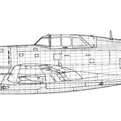
layer with your UV-map (the one created in the previous step). Now create a new layer with drawing we used in the reference setup on top of the UV-layer. You will probably have to scale & stretch
it a bit to fit the UV-map. Create new blank layer on top - name it "bump" for example. Make both the bump layer and drawing layer transparent (lower the layer opacity) so that
you can make out the UV-map. The reference drawing has all the panel lines (and rivets) so you can easily see where to paint your bump (in the bump layer). I use a 2048*2048 canvas and a 2 pix black brush (not pencil) to draw the lines.
Save as "bump.jpg".
|
|
|
Basic color layer
This is also easy - just paint green where it should be green, grey where it should be grey and blue where it should be pink etc (hehe just kidding - blue where it should be blue). Don't worry about details yet - just get the color areas right. Search the web for reference photos, or even better illustrations.
|
|

|
3D enhancing layer 1
Even though we're texturing a 3D object we still need a trick or two to enhance the 3D feeling. Light your bump layer and make a copy if it and place it _under_ the original bump layer. Blur it a bit using Gaussian blur and name it "bump blur". Make another copy of the original bump layer and place it on the top. Name it "bump light" , invert it (the lines should be white now) and move it 1-2 pixels to the right and then 1-2 pixels to the top.
|
|

|
Details layer.
Add markings, texts, gradients and other texture details in this layer.
|
|

|
Dirt layer
Use a big soft low opacity brush to paint the dirt. It's likely to be dirty around exhaust, engines, guns, edges of moving parts etc.
Damage layer
The aircrafts paint is most probably more or less damaged / worn. Select a soft low opacity brush and paint on the borders of the objects that you wish to make look worn or weathered. Use light grey or a lighter color of the one you are currently painting over.
|
|

|
Paint is likely to chip of around rivets, panel edges, maybe around the cockpit and other exposed area. I have painted these jaggy shapes in such areas. I made the basic color layer a bit transparent so that I can see where the edges are.
You can combine the bump & damage layer if you wish to enhance the damage in the render and use the combination in your bump, diffusion or specular color channels.
|
|

|
3D enhancing layer 2
Enhance the 3D-feeling by adding shadows between plates and between parts that move (for example flaps). The easiest way is to use some kind of drop shadow function/plugin for this.
|
|

|
Structure layer
You can get rid of the polished look by creating a new layer and fill it with a dark brownish color. Add a lot of noise and turn up the contrast - play around. Set the layer to screen mode and lower the opacity. I personally think that this step adds structure to the textures makes the texture look more realistic once applied.
|
|

|
Test render.
Please send me more texturing tips and I will add them to this page!
NEXT CHAPTER: "Poserizing" and rigging the model in poser.
|
|
|
|