| Renders & Downloads | Who is & Info | Links | Home |
|
UV mapping tutorial (for Modo) |
|
Introduction In this walkthrough I’m going to show you how I usually go about when I unwrap a non-organic mesh in Modo. This piece isn’t for total Modo beginners and I assume you are fairly familiar with Modo tools, viewports etc. Organic meshes are really easy to unwrap in Modo – you simply select the edges/loops where you want to cut and then basically all you have to do is hit relax and/or unwrap. This piece is about a technique for unwrapping non-organic objects by splitting them into smaller UV-parts that later are stitched back together. The smaller parts are unwrapped in different ways depending on their topology. Some terms that I use: N-gon = Polygon with more than 4 corners (should generally be avoided) UV-island = Chunk of connected polygons in the UV-viewport Frozen mesh = Mesh that has been made editable (i.e. frozen) from Sub-D mode. (Updated) At the very bottom of this page I'm describing an alternative way of aligning edges. |
|
Let's start... This is the mesh I’m going to unwrap. You can download it from here [link to Modo lxo file]. It is only a part of the PZL p11 model (the cowling) but is a good example for the technique I want to show. I can’t unwrap it like an organic mesh because I want straight and aligned UV-islands (not banana-shaped UV-islands) that will make it easy for me to paint panels and rivet lines. Example UV-map created using this technique [here] 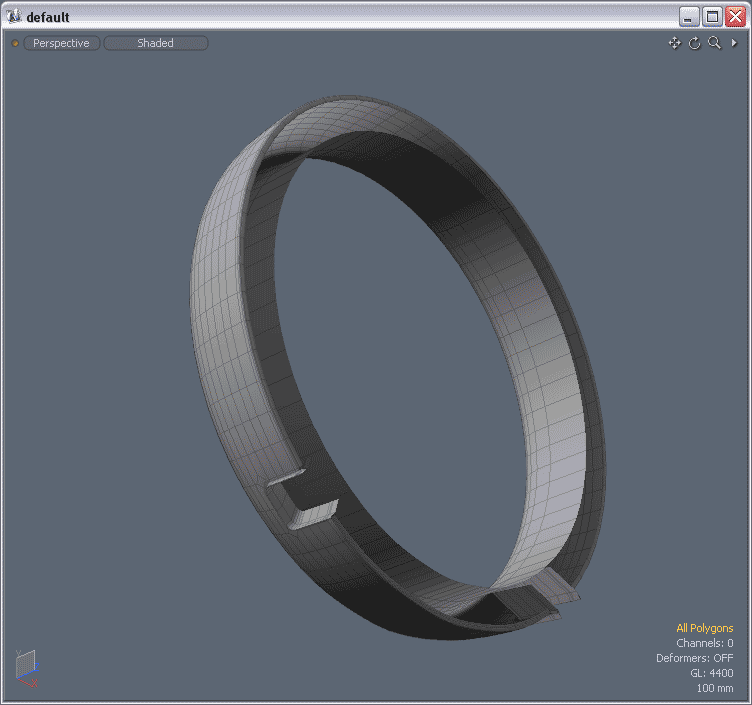 OK.. this object isn’t super complicated but it can be tricky to UV-map because it is circular, bends inwards…
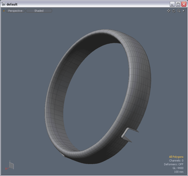 ..and also has these two areas at the bottom half that are cut out with extruded and beveled edges.
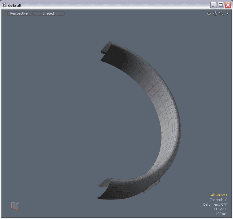 The object is symmetrical so let’s delete half of it and only worry about unwrapping this half. I usually go to front or top view, select all vertices of one side of the X-axis and hit the delete button.
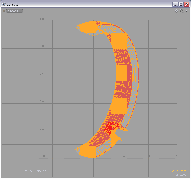 To get started align your object in the 3D viewport, click on “Project from view” (in UV-tools) and then click somewhere in the 3D viewport. Your result in the UV-viewport could look something like this.
I assume that you have created a new UV-map prior to this step.
To get started align your object in the 3D viewport, click on “Project from view” (in UV-tools) and then click somewhere in the 3D viewport. Your result in the UV-viewport could look something like this.
I assume that you have created a new UV-map prior to this step.
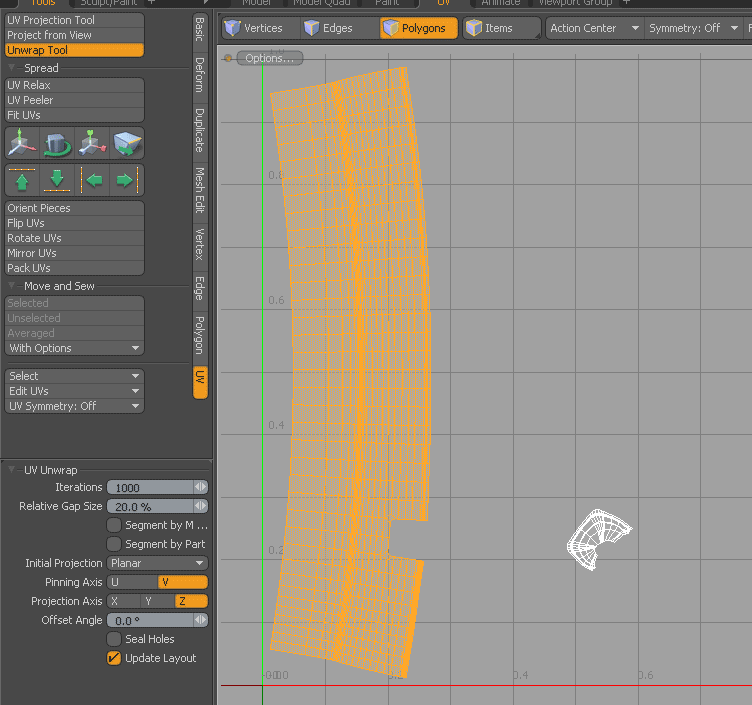
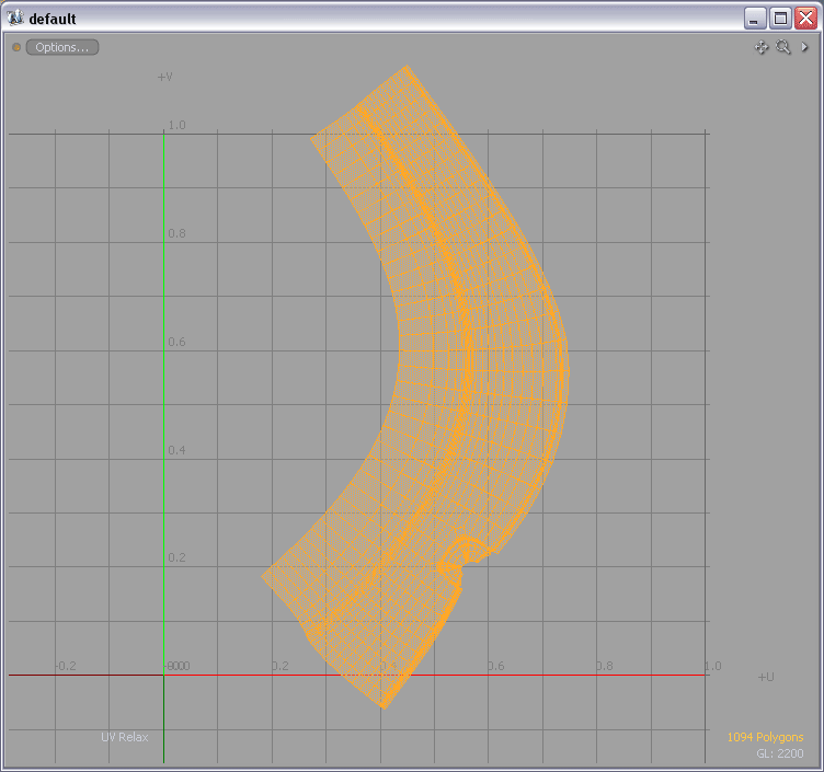 Click on “UV Relax” with number of iterations set to about 1000. The result is a crooked but unwrapped and now we can start making it into a usable UV-island.
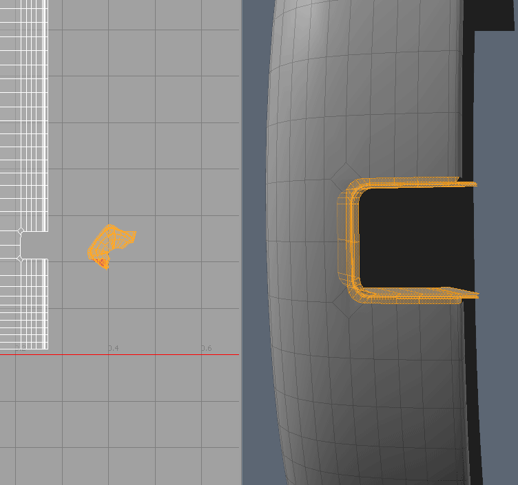
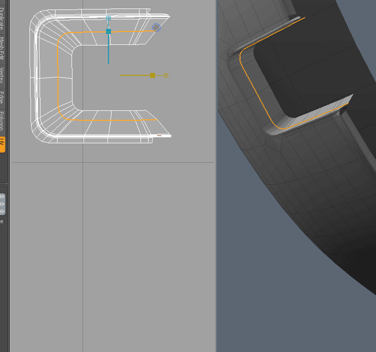
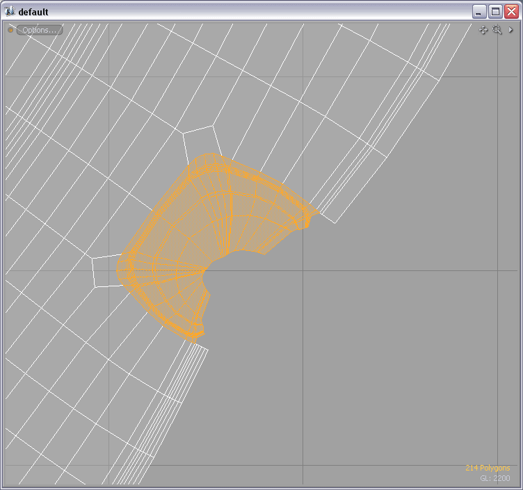 Zoom in on the “hole” and select these polygons.
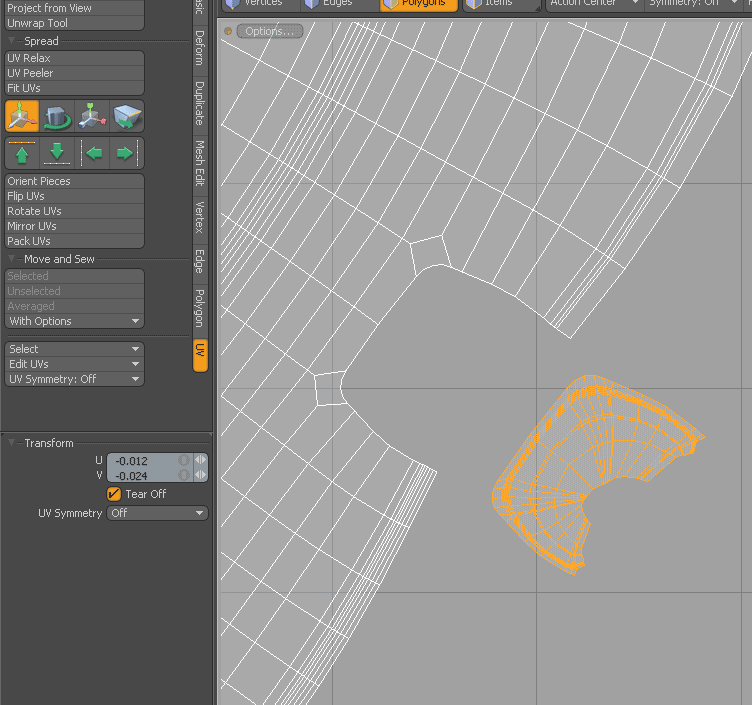 Select the move tool (in the UV-viewport), check “Tear Off” and just move this smaller piece of the UV-island away from the rest.
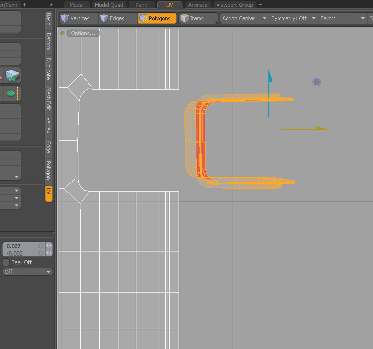
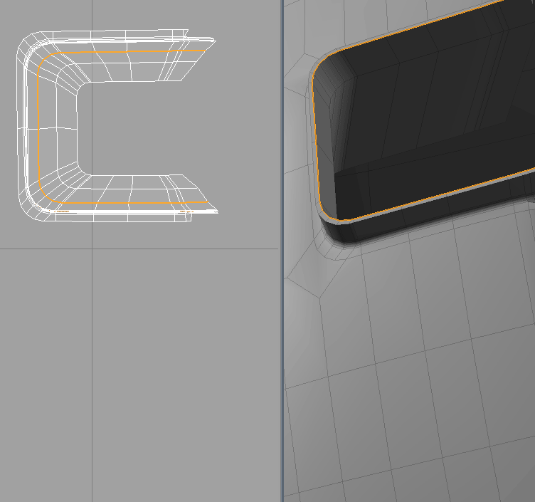
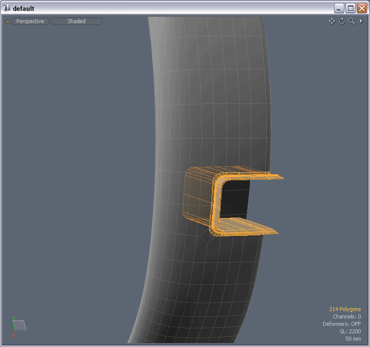 Make sure you just separated it from the main UV-island in the UV-view. Your mesh in the 3D viewport still should look something like this.
 Click on the Unwrap tool and apply it (set the iterations to about 1000). Your result should look something like this. If needed rotate the UV-island slightly.
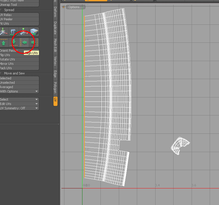 Now let’s start aligning the edges/loops. Select edge to the left and click Align UVs (left). Select the next edge and align in to the left, then the next etc etc. This goes really quick if you use the left/right arrows for selecting next/previous edge and use ctrl+R to repeat the last command.
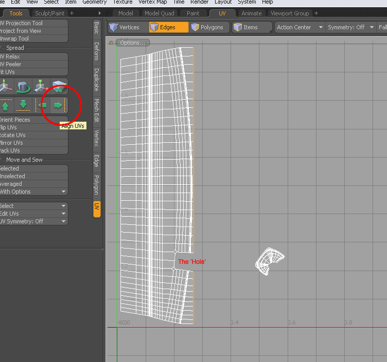 Repeat the above steps until you reach the “hole”. Then select the outer right edge and go through the same procedure for each edge but align them to the right instead.
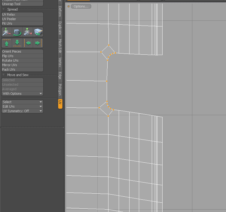
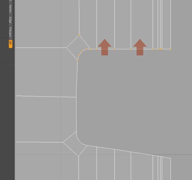
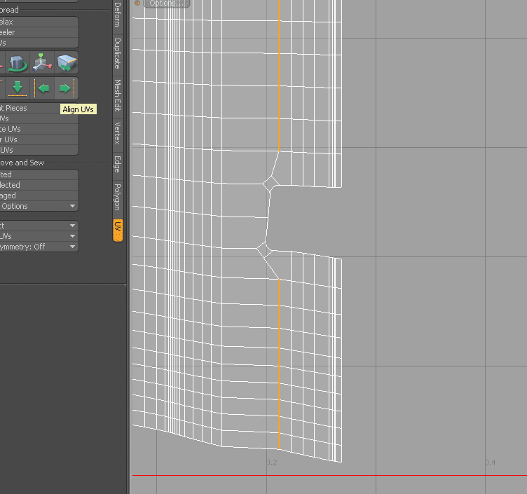 The two selected edges in this image have to be aligned separately. I’m not sure why but I guess the two N-gongs in the corners of the “hole” make the align command go bananas. No big deal, select the upper edge and align it to the right and then do the same to the lower edge.
 This image shows that I selected these vertices and manually aligned this part of the UV-map.
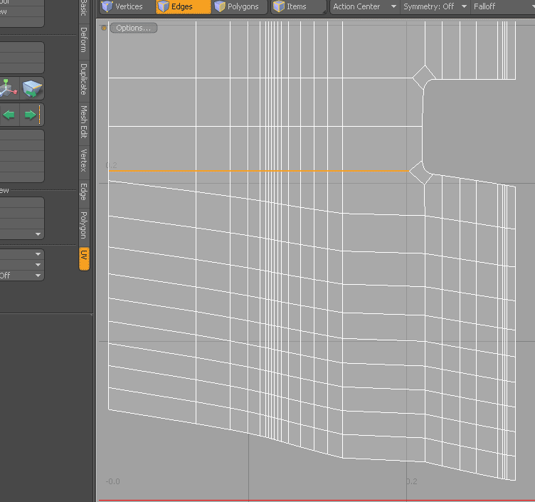
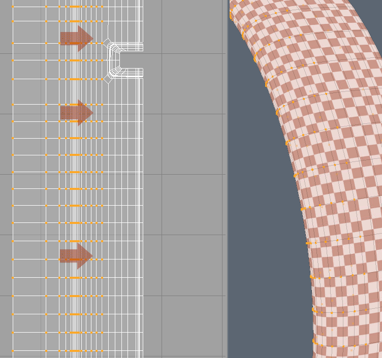
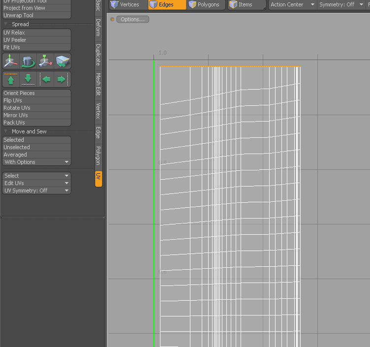 Now you should have a UV-island with all vertical edges nicely aligned and parallel. Let’s carry on with the horizontal ones. Select the upper most edge end align it upwards. Work your way downwards aligning edges (remember to use quick-keys for selecting next edge [left/right arrow] and for repeating the align command [ctrl+r]) until you reach the “hole”.
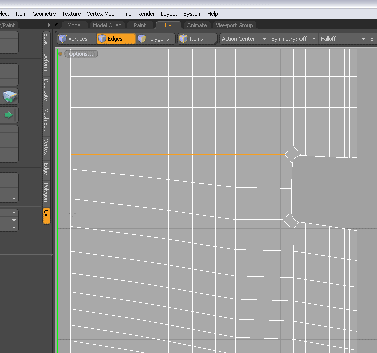 Select the edge to the left of the N-gon and align it upwards…
 …then select the edge to the right of the N-gon and align it upwards.
 You might need to select these vertices and move them up to align the edges to the left and right if the N-gon.
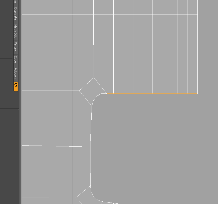
 Align this edge separately…
 …and then this. Move it up to align it with the edge to the left of the N-gon.
 Work your way downwards aligning the remaining horizontal edges. When you’re done you should have a nicely laid out UV-island looking something like this. The next step is to take care of the small part that was separated/torn off in the beginning.
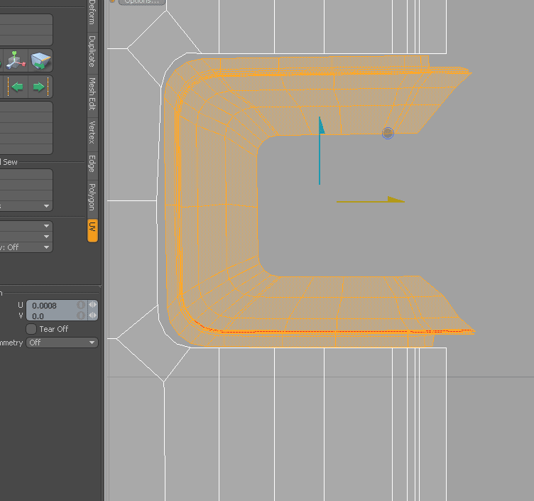
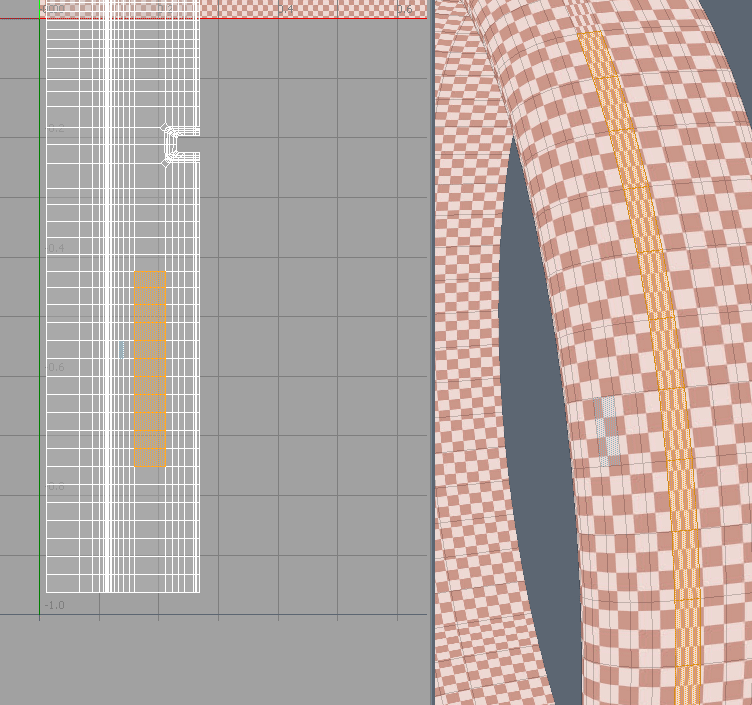
 Select all the polygons of the small separated part and adjust the camera in the 3D viewport to look something like in this image. Select “project from view” and click in the 3D viewport
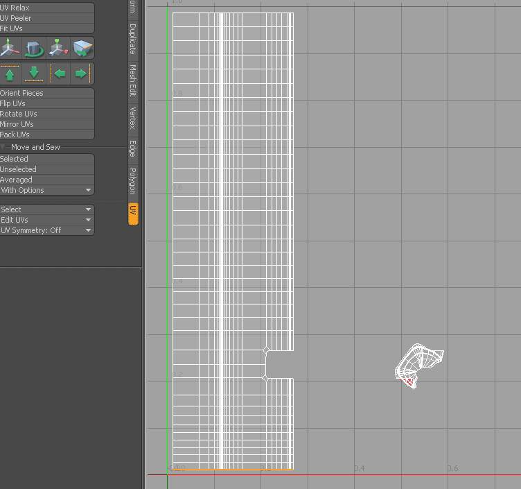
 Scale down the smaller UV-island so that can be fitted into the hole later on.
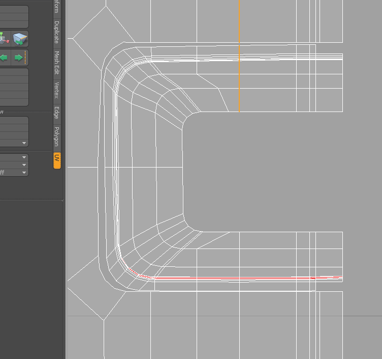
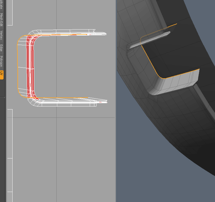 There are some overlapping polygons (red) in this piece since it was just “projected from view” without any relaxing. Let’s relax it manually too keep its shape but get rid of some of the overlapping polygons. Select this edge…
 …and scale/move it into this position.
 Select the next edge and scale/move it in a similar way.
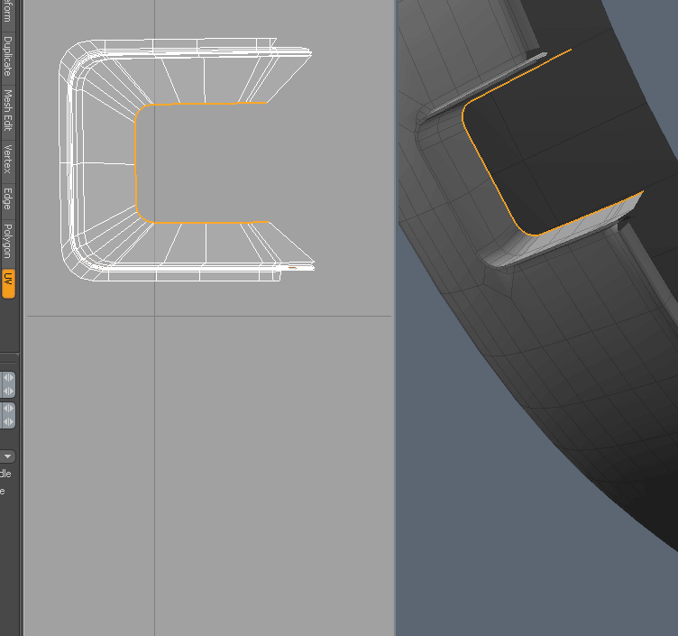
 And the same thing with the next edge. Continue if you wish but I stopped here even though there still are some overlapping polygons in the UV.
 Move the small UV-island into the hole of the big one.
 Using the UV-align tool align the edges of the smaller uv-island to the ones of the bigger uv-island and generally clean it up.
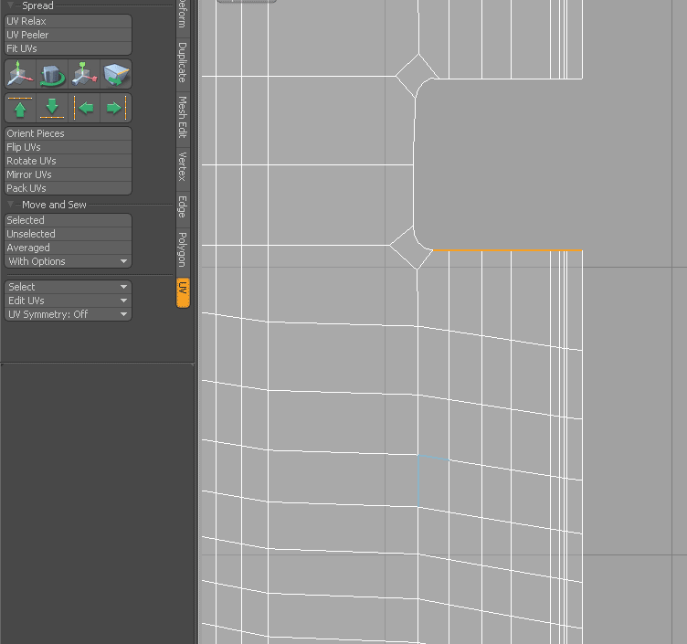
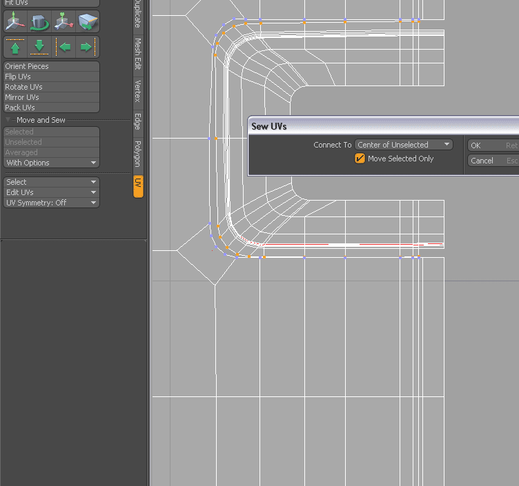 Select the outer vertices (the corresponding ones will be marked with blue) and click on “Move and Sew/With options”. In the pop up select “Move Selected Only”.
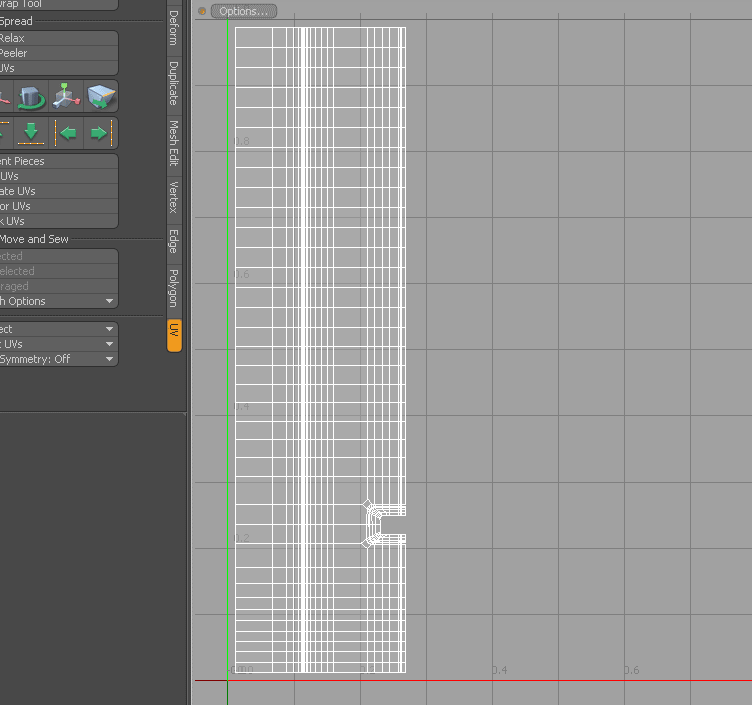 Now you should have one nicely connected and aligned UV-island looking something like this.
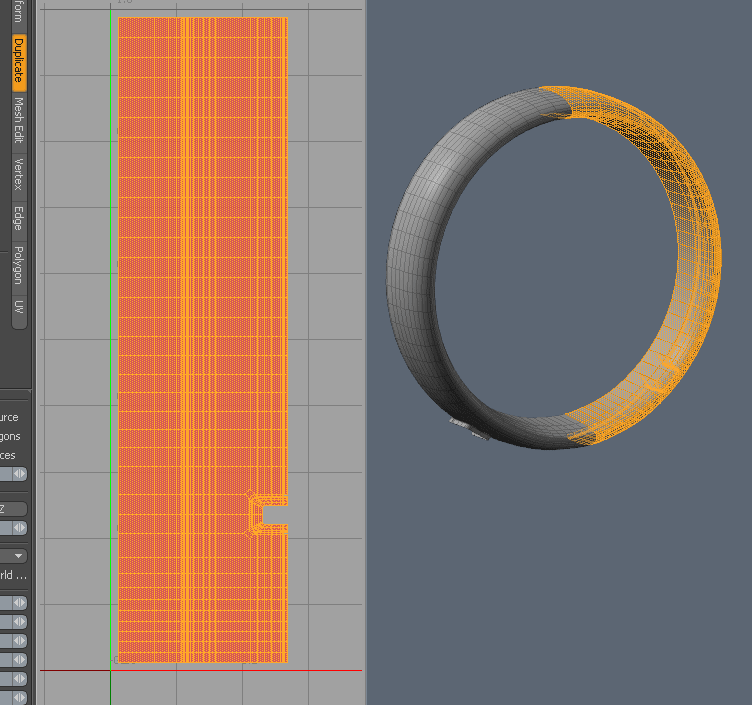 Select all the polygons and click on “Mirror” (under the duplicate tab). The cowling is now whole again but not uniquely UV-mapped on both sides.
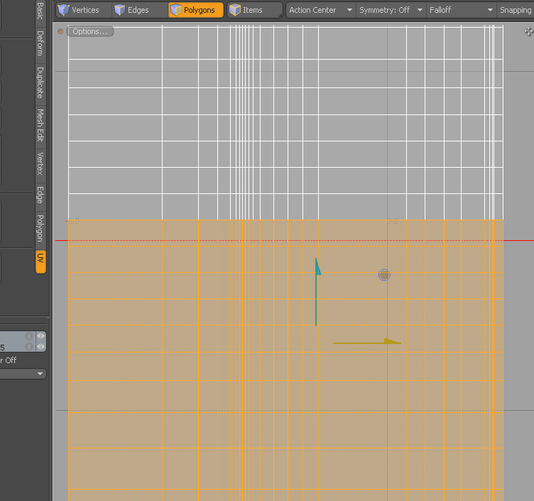
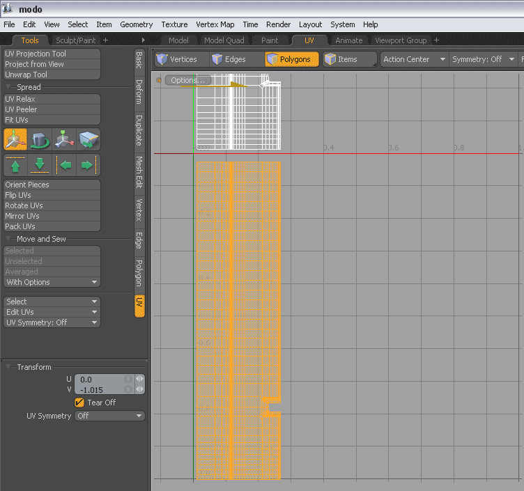 Don’t deselect the new polygons but move them down using the move tool (in the UV-window). Make sure that you move them straight down without dodging a single pixel left or right. “Tear off” should be checked.
 You now have two UV-islands. Mirror the below one by scaling it -100% in the V-axis.
 Move it up and align it to the first one. Use the stitch and sew tools to stitch the two UV-islands back together.
 Apply a checkers texture to make sure that there will be as little distortion as possible and that the relative scale is correct (i.e. all squares are square and about the same size). In this picture you can see that the row of polygons (selected to the left) have too much UV-space. This is fixed by…
 …selecting the vertices to the left and moving them slightly to the right.
Voilá! Now you have a nicely unwrapped mesh that will be very easy to texture without worrying about having to compensate for distortion! Alternate way of aligning edges There's a pretty smooth alternative for how several edges can be aligned simultaneously. Thanks to members of the Luxology forum for making me aware of this (link to thread) I'm describing it below with some new screenshots (now from Modo401): 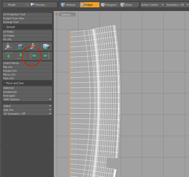 Select the outer edge. Align it it usign the "Align UVs" command.
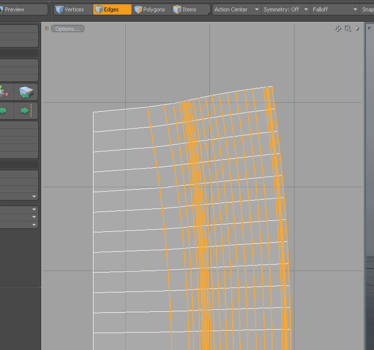 Then select the rest of the edges that you wish to align/straighten out.
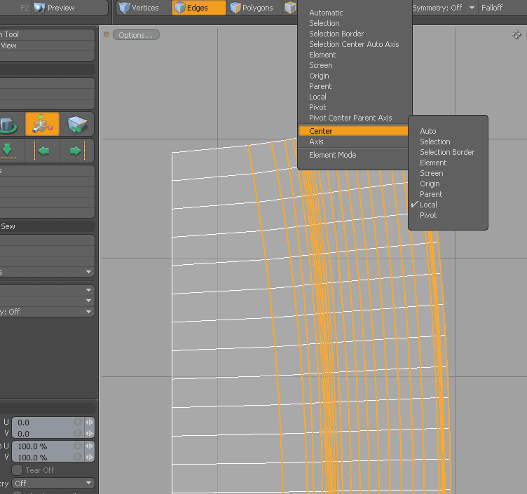 From the "Action Center" menu select Center -> Local...
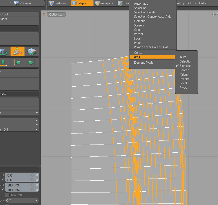 ...and Axis -> Element.
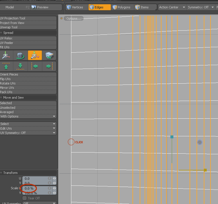 Select the scale tool and click on the outer edge you just aligned. Set the Scale U value to 0% or do this manually by dragging the yellow control gizmo.
|